Update: The Python script to generate these flexible designs, along with examples and instructions can be found here: Generating Flat Flexible Soldered Cable Designs.
During a past project I had to connect two PCB’s with multiple connections over a moving part. Normally this leaves two options:
- Flexi-Rigid PCB’s – Good, but can be fragile, often expensive and size limited due to tolerances.
- Some type of connector / cable system. This could be a FFC, ZIF, IDC system or similar. Usually quite expensive and normally not designed for movement.
Here’s the solution I developed for the project:
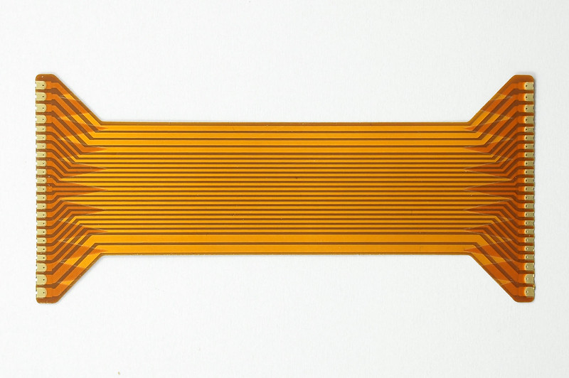
It’s a multi-layer flexible / Kapton / polyimide film PCB designed to be soldered directly to two rigid PCB’s. The key feature in the design is the addition of layers with a tapered or zig-zag design. This distributes the stress instead of creating a folding point at the edge of the rigid PCB. The additional layer makes it particularly strong at this point.
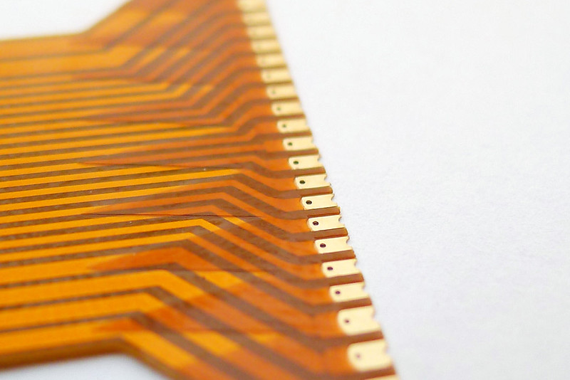
The pads are designed with a few details that make it quick and easy to solder. The top Kapton layer overlaps the pads with a radius, castellated ends are used and vias are present in the middle of the pads. These features allow the solder to easily flow under and through to the underside.
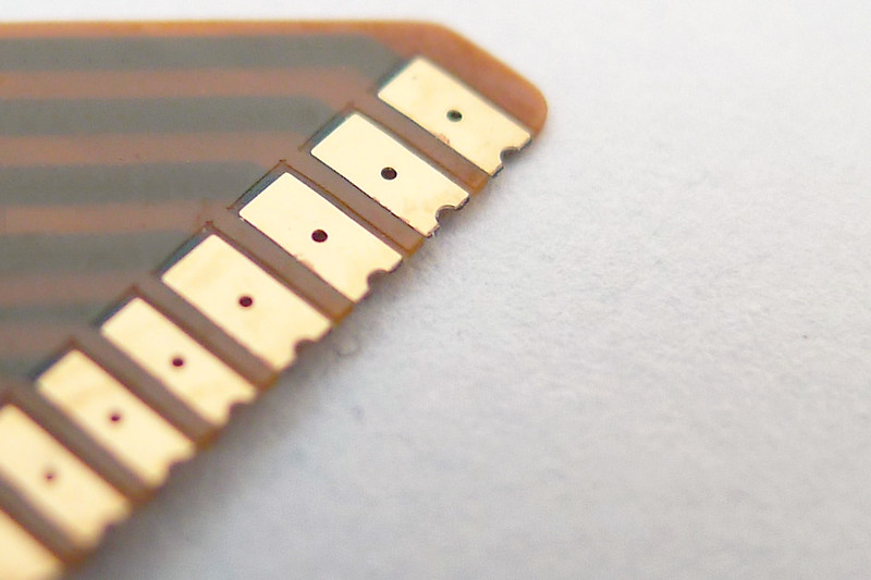
The underside pad shape is extended to match the rigid PCB footprint.
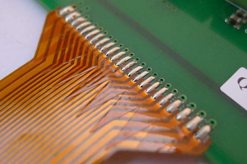
Once soldered, it gives a solid joint that is extremely durable. It can be soldered at any angle, giving more design freedom in positioning the PCB’s. It worked out quite a bit cheaper than any other alternative in this application, even after the additional assembly process. It is particularly suitable for any application that requires high reliability.
To simplify the process I have written a piece of software that generates the connector design as an Eagle script from a range of parameters automatically.
Hello, what current is it designed for? Could it be rated for 8.5-10A current?
How the soldering process is performed? can it be automated? in the later case, what considerations should we take into account (i.e. cleareance of components near the pads, etc)
How are the pads connected to the ribbon?
The pads are literally the same piece of copper as the tracks – The kapton covers both sides, but leaves an area used for the pads. These are then gold plated, ready for soldering.
Where did you have these manufactured